8. Textures of Liquid Crystals
The knowledge of the relations between structures and their textures are necessary for understanding of the liquid crystals structures from their optical microscopy textures.
Usually, for basic studying or practical application, liquid crystal is filled in between two glass substrates. As we already know, the certain treatment of the substrate surfaces allows one to obtain different types of LC orientation. In the case of heterogeneous planar orientation of nematics, the director n is parallel to substrates but points in different directions. Such a structure appears as a schlieren texture between crossed polarizers in a polarizing microscope (Fig.21).
|
|
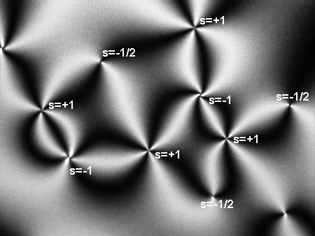
Figure 21. Schlieren texture in nematic liquid crystal |
The schlieren texture
shows dark brushes, which correspond to the extinction orientation of
the nematic LC. Accordingly, the director n lies either parallel or perpendicular to
the polarizer or analyzer axes. The points, where two or four brushes meet,
correspond to the director singularities and are called disclinations in the structure.
The disclination is characterized by its strength s, which shows how much the
director rotates in each point on the closed curve around the singularity
point. The disclinations with s=±1/2,±1 can be found in nematics.
The points where four brushes meet correspond to the disclinations
with s=±1, and, the points with two brushes correspond to
the disclinations with s=±1/2. Usually, neighboring singularities which are connected by brushes have opposite signs (Fig.21).
To distinguish between the disclinations of different sign, one can use, for example,
the rotation of the sample with schlieren texture between the fixed crossed polarizers (Figs. 22 and 23).
When the LC sample is rotated, the black brushes move continuously indicating
a continuous change of the director n.
Both two- and four-brush disclinations with a negative sign rotate in the same
sense as the sample (Figs.22a and 23), but the brushes of positive two-brush disclinations rotate in the opposite sense (Fig. 23). The orientation of brushes of positive four-brush disclinations with s=+1 does not change upon rotation of the sample between the fixed crossed polarizers (Fig.22b) (see also Ref.1 for details).
(a) |
(b) |
||
|
Figure 22. Rotation of a nematic liquid crystal sample between fixed crossed polarizers to distinguish the sign of four-brush disclinations with (a) s=-1 and (b) s=+1. Polarizer and analyzer are parallel to the horizontal and vertical edges of the image, respectively. | |||
|
Figure 23. Rotation of a nematic liquid crystal sample between fixed crossed polarizers to distinguish the sign of disclinations s=±1/2 |
One can also fix the LC sample and rotate the crossed polarizers. In this case, the brushes corresponding to positive disclinations rotate in the same sense and the brushes corresponding to negative disclinations rotate in the opposite sense to rotating polarizers (see Ref.1 for details).
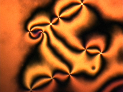
Electric fields applied along the homeotropically aligned nematic LC with the negative dielectric anisotropy also can produce schlieren textures (Fig.24) where the defects with s=±1/2 do not appear.
|
|
Figure 24. Schlieren texture caused by electric field applied to homeotropically aligned nematic liquid crystal with Δε<0 |
In the case when the nematic LC sample with the homogeneous planar alignment placed between two crossed polarizers, the texture appears completely black when the director direction is either parallel or perpendicular to the transmission axis of the polarizer or analyzer (Fig.25).
|
Figure 25. Uniform nematic liquid crystal cell between crossed polarizers |
The intensity of the transmitted light through a system polarizer - planar nematic - analyzer depends on the angle β between the LC optical axis and polarizers as I∝sin22β and reach the maximum when β=45o (Fig.25).
[1] S. Chandrasekhar, Liquid Crystals, 2nd ed. (Cambridge University Press, 1992), Ch. 3.5
Prev
LCs in external fields
Next
Textures of cholesterics