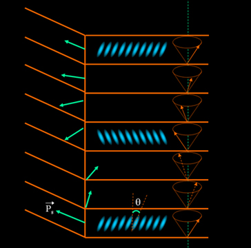
Ferroelectric
liquid crystals consist of chiral smectic A and smectic C. They are
intrinsically chiral or with addition of chiral dopant. The chiral smectic C
phase is also called smectic C*. The molecules align along a helix; symmetry
consideration requires that a spontaneous polarization Ps should be present. The
LC configuration is a layered structure, and the layer boundaries are parallel
planes; but the boundaries are not necessary perpendicular to the substrate. In
each layer the molecules are parallel to each other.
Figure 1. The
layer structure of ferroelectric liquid crystal.
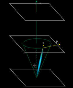
There are two
stable positions for LC molecules to stay. The positions lie on a cone with an
angle of 2θ, and θ depends on temperature. The spontaneous polarization Ps
is perpendicular to the director, and tangential to the circle of intersection
of the cone with the boundary plane of the layer.
Figure 2. The
molecule orientation with respect to the layer.
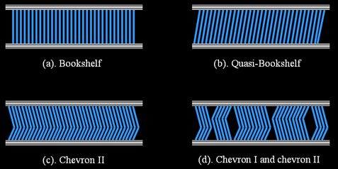
The total sum
of all Ps is zero within one pitch. In order to use the Ps for display
application, the helix should be suppressed. The Surface-Stabilized FLC was
proposed by Clark and Lagerwall to supress the helix. The cell gap is only
1-2μm, and surfaces are treated to make the layer normal to the substrates. With
this configuration, four different LC orientations can appear which mainly
depend on the pretilt angle at the surface, as shown in figure 3.
Figure 3.
Different layer orientation for surface stabilized ferroelectric liquid crystal.
The net
polarization Ps in SSFLC cells is perpendicular to the substrate. If we apply an
electric field, the Ps will couple with the field; therefore the molecule will
tilt up and down, as shown in animation 1.
Animation 1.
Schematic illustration of SSFLC display.
At the off
state, the molecule is parallel to the polarizer, and therefore there is no
transmission after crossed polarizers. When the field is on, the molecule will
change to the position which is the across the cone, and the angle between
polarizer is no longer zero, so transmission is observed.
The switching
speed is very fast, which is usually a few micro seconds. The two states are
bistable which means the field is not required once the tilting is finished.
However the SSFLC does not own the capability of gray scale. Since the switching
speed is fast enough, digital gray scale can be achieved.
Further Readings
and References:
N. A. Clark and S.
T. Lagerwall, “Submicrosecond bistable electro-optic switching in
liquid crystals”, Appl. Phys. Lett. 36, 899-901 (1980).
P. Watson, P.J. Bos, J. Pirs,
"Effects of Surface Topography on Formation of Zig-Zag Defects in SSFLC
Devices", SID digest, p743 (1997).
Last
update: April, 2006
Questions? Contact author.