ˇˇ[Multi-domain Vertical Alignment (MVA) mode]
In the basic VA mode, the molecules can tilt
towards to any directions because of the lacking of in-place easy
axis, therefore the umbilics defects appear, which is not desired in
the display application because it not only produces transmission
fluctuation but also slow down the response time.
In order to control obtain a symmetric viewing angle, the
pixel is divided into domains, where the LC molecules will have pre-determined
tilt directions. The multi-domain are obtained by introducing protrusions on
both substrates. This is the Multi-Domain VA mode (MVA).
In the off state, the LC molecules are perpendicularly
aligned, hence no transmission after crossed polarizers, this is the black
state. In the on state, the LC molecules tilt in a direction controlled by the
protrusions, a phase retardation is present to the incoming light, and
transmission is not zero after the exist polarizer; at high field, the LC
molecules in the mid-layer are all parallel to the substrate surface, a higher
transmission is obtained.
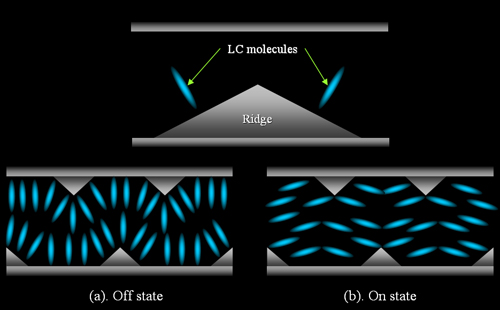
Figure 1.
Operating principle of Multi-domain Vertical alignment LCD
The MVA was first introduced by Fujitsu, and now adopted
by a few manufactures. It can give very good viewing angles because of the
symmetric LC domains. The MVA mode eliminates the need for a rubbing process,
which makes manufacturing simpler and the MVA-TFTs more stable.
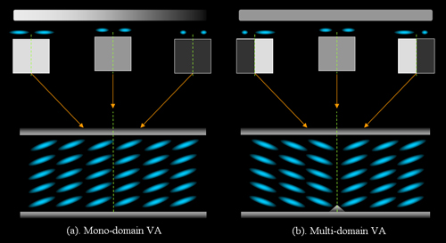
Figure 2.
Viewing angle comparison between Mono-domain VA and Multi-domain VA.
Later improvement to the original MVA mode is to replace
the protrusions on one substrates with patterned ITO slits. This improvement not
only reduce manufacture steps, but also increase the contrast ratio since the
residual birefringence around the protrusions on one substrate is removed. A
brief comparison of performance between original MVA and improved MVA mode is
listed in the following table.
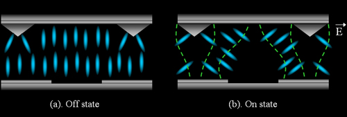
Figure 3. Director and pixel
configuration comparison between original MVA and improved version.
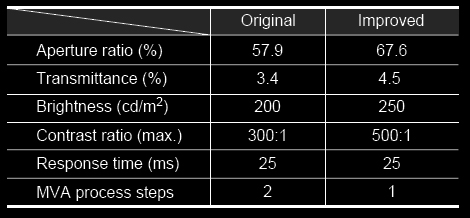
Figure 4. Performance comparison
between original MVA and improved version.
Further Readings
and References:
A. Takeda, S.
Kataoka, T. Sasaki, H. Chida, H. Tsuda, K. Ohmuro, T. Sasabayashi,
Y. Koike, and K. Okamoto, ˇ°A super-high image quality
multi-domain vertical alignment LCD by new rubbing-less technology,ˇ±
SID Dig., pp. 1077¨C1100 (1998).
Y. Tanaka, Y.
Taniguchi, T. Sasaki, A. Takeda, Y. Koibe, and K. Okamoto, ˇ°A new
design to improve performance and simplify the manufacturing process
of high-quality MVA TFT-LCD panels,ˇ± in SID Dig., pp. 206¨C209
(1999).
Y. Koike and K.
Okamoto, ˇ°Super high quality MVA-TFT liquid crystal displays,ˇ±
Fujitsu Sci. Tech. J., vol. 35, pp. 221¨C228 (1999).
ˇˇ